Boilers
Lafil - Steam Jet Boiler
Thermic Fluid Heater
Hot Air | Steam | Water Generator
Steam Jet IBR Approved

TECHNICAL SPECIFICATIONS
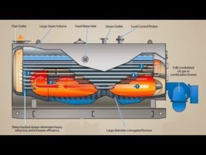
THREE PASS OIL/GAS FIRED FULLY AUTOMATIC SMOKE TUBE STEAM BOILER
TECHNICAL SPECIFICATION:
i – Type – Horizontal, 3 pass, Fully Wet Back , IBR approved Smoke Tube boiler.
ii – Capacity – 1000 Kg/hr to 60000 Kg/hr (F & A 100° C)
iii – Working Pressure – Std. 10.5 Kg/cm2 (g), 14.06 Kg/cm2 (g), 17.05 Kg/cm2 (g) and above with water tube design also available.
iv – Fuel – Gas / Diesel/Heavy Oil/ Dual Fuel
v – Thermal Efficiency – 88% + 1% based on N.C.V. of fuels 92% + 1% based on N.C.V. of fuels with Heat Recovery Unit
vi – Heat Recovery Unit – Economiser/Air Preheater
vii – Burner – Fully Automatic, Pressure Jet with High-Low/Stepless Modulation
UNITS MANUFACTURED AS PER LATEST INDIAN BOILER REGULATIONS
CONSTRUCTION
i – Three pass horizontal smoke tube economic shell type Boiler
ii – Designed and Fabricated in accordance with Indian Boiler Regulations (IBR)
iii – Stage inspected, hydraulically shop tested and certified by Director Steam Boilers .
iv – Wet back construction having very good heat absorption in the radiant heating zone.
v – Furnace is provided with a large radiant heating surface maintaining safe furnace wall temperatures much below its safer limits
vi – Furnace volumes liberally selected ensuring complete combustion and highest combustion efficiency
vii – Steam and Water space is quite large providing ability to respond to fluctuating loads effectively
viii – “LAFIL” has its own superior design standards which are governed by Internationally laid down sound design parameters
ix – Design range up to 60000 Kg/hr (F & A 100° C)
OPERATION
i – The Burner is FULLY AUTOMATIC PRESSURE JET TYPE having either HIGH-LOW, ON-OFF modulation or continuous STEPLESS modulation
ii – Burner is SELF IGNITING and maintains CLEAN and SMOKELESS COMBUSTION all throughout the operation
iii – The outlet flue gas temperatures are optimum such that the thermal efficiency is highest and problems due to H2SO3 condensation are not observed (due to high Sulphur content in the furnace Oil)
iv – The Burner function is suitably integrated with the control panel such that in case of any abnormal operating condition the Burner will cut off safely and will go to safety lockout condition by giving Audio Visual Annunciation and Alarm.
SAFETY FEATURES
i – Low Water level cut out
ii – Flame failure lock out
iii – Steam safety valve
iv – Back fire pressure relief
v – Fusible plug
OUR DESIGN AND PERFORMANCE ADVANTAGES
i – High thermal efficiency of 88% on NCV of fuel Oil over entire operating range
ii – High Steam space in the Boiler and large Steam release area on Water surface gives better quality of dry Steam
iii – Priming and foaming tendencies are totally eliminated ensuring long life of Steam pipe line with no deposits inside
iv – The plant will have highest integrated Steam/circuit efficiency
v – High furnace volume ensures long furnace residence time and complete combustion of fuel at low excess Air
vi – Better Combustion efficiency with soot free combustion and guarantee of highest CO2%
vii – High furnace volume and large radiation surface giving very high heat absorption in furnace and also simultaneously keeping moderate heat flux and heat release rates (Heat flux + Heat release per m2of furnace area and Heat release rate + Heat release per m3 of furnace volume)
Moderate heat release rate/heat flux ensures low thermal stresses and safe furnace metal temperature
OPTIONAL
To achieve the highest fuel saving, the provision is made to incorporate the AIR PREHEATER. This preheats the Air before being fed to combustion. An additional 5% of thermal efficiency can be achieved by this feature.
OIL | GAS | DUAL FIRED FULLY AUTOMATIC THERMIC FLUID HEATER
Technical Specifications | Construction
i – Type – Vertical/Horizontal, 3 pass, Coil Type Thermic Fluid Heater
iii – Temperature – Up to 300°C and above
v – Thermal Efficiency – 88% + 1% based on N.C.V. of Fuels
vii – Air Preheater – In-built …
ix– Spirally wound heating coil concentrically placed within the assembly formed by outer shell and inner shell
xi– Heating coil manufactured out of SEAMLESS PIPE confirming to ASTM – A – 106 Grade B standard
xiii– Burner components and Air Cone manufactured out of heavy gauge STAINLESS STEEL sheets
xv– The control panel is SWITCH GEARED with easy available standard components from market to increase independence
ii – Capacity – 50000 kcal/hr to 2500000 kcal/hr and above
iv – Fuel – Gas / Diesel/Heavy Oil/ Dual Fuel
vi – Heat Recovery Unit – Economiser (Optional)
viii – Vertical / Horizontal Coil type 3 pass Gas / Diesel/Heavy Oil/ Dual Fuel fired Thermic Fluid Heater
x– The passage between inner shell and outer shell provided with the Radiator along with the Radiator itself act as a Combustion Air Preheater
xii – Coil hydraulically tested for pressure of 55 kg/cm2 applied for about 30 minutes
xiv – Blower provided with statically and dynamically balanced impeller for smooth operation
xvi – The control panel is WIRED with solid Copper Conductor wires for easy tracing of control circuit adding further independence
Operation | Safety Features
i – Fully automatic operation with BURNER ON-OFF modulation for units up to 40 Lac kcal/hr and HIGH-LOW ON-OFF modulation for higher capacity units keeping FUEL CONSUMPTION in proportion with heat demand in the plant
iii – Burner is self igniting and maintains CLEAN and SMOKELESS COMBUSTION all throughout the operation
v – Hot Oil circulation pump is of centrifugal type maintaining the circulation of Hot Thermic Fluid through heating coil .
vii – In case of any abnormal operating condition the SAFETIES provided stop the unit and put the same to SAFETY LOCKOUT CONDITION by giving AUDIBLE ALARM and VISUAL INDICATION
ix – Thermic Fluid low flow tripping
xi– Blow down valve
vi – Miniature Circuit Breaker for control circuit
xv– High stack temperature Annunciation/Alarm (optional)
x – Control circuit logic ensures Heater going to lock out safety in case of any abnormality in operating condition as well as monitoring instrument failure
ii – The Burner is pressure atomizing type and is centrally located at the top of the unit .
iv – Preheated combustion Air gives highest Combustion efficiency maintaining high CO2 % and Low Smoke Index
vi – A Digital Temperature Controller senses the heat demand in the plant and controls the Burner ON-OFF/HIGH-LOW modulation maintaining minimum fuel consumption
viii – Flame failure device .
x – Overriding temperature tripping
xii– Single phasing prevention cum over load for control circuit
xiv– Thermic Fluid level switch on expansion tank (optional)
ix – Fail Safe Instrumentation
Cumbustion and Heat Transfer
i – High furnace volume for long furnace residence time ensuring complete combustion of fuel at low excess Air
ii – The Smoke Index is considerably low with low excess Air improving Combustion efficiency
iii – Large radiation surface giving very high heat absorption in furnace with moderate heat flux and heat release rate
iv – Three pass design giving highest total length of passes and longer residence time of flue gases
v – Overall thermal efficiency of 88% on NCV of fuel Oil
vi – The overall thermal efficiency is subject to return Oil temperature from process (minimum return Oil temperature means maximum thermal efficiency)
STEAM PACK (IBR | NON - IBR)
Gas / Diesel/Heavy Oil/ Dual Fuel FIRED FULLY AUTOMATIC HOT AIR / STEAM GENERATOR
Technical Specifications | Construction
i – Type –4 Pass Vertical, Non-IBR Coil Type Instant Steam Generator
.
iii – Working Pressure – Up to 15 kg/cm2 (g) and above
v – Thermal Efficiency – 93% + 1% based on N.C.V. of Fuels
vii – Dryness Fraction – 0.9
ix – CONTAMINATION FREE PHARMACEUTICAL / FOOD GRADE HOT AIR AVAILABLE
. xi – Vertical Coil type forced Water circulation instant Steam / Hot Air Generators. .
xiii – The passage between inner shell and outer shell provided with the Radiator along with the Radiator itself act as a Combustion Air Preheater.
xv – Steam Coil hydraulically tested for pressure of 55 kg/cm2 applied for about 30 minutes.
xvii – Blower provided with statically and dynamically balanced impeller for smooth operation.
xix – The control panel is SWITCH GEARED with easy available standard components from market to increase independence.
ii – Capacity – 100 kg/hr to 850 kg/hr F & A 30° C
100 kg/hr to 1000 kg/hr F & A 100° C
iv – Fuel – Gas / Diesel/Heavy Oil/ Dual Fuel
vi – Heat Recovery Unit – Economiser
viii – Air Preheater – In-built
x – UNITS FIRED WITH AGRO BASED FUELS LIKECOAL / WOOD / BAGASSECANBEOFFERED
xii – Spirally wound Steam Coil concentrically placed within the assembly formed by outer shell and inner shell.
xiv – The material of construction for Steam Coil is BOILER QUALITY STEEL. .
vi – Burner components and Air Cone manufactured out of heavy gauge STAINLESS STEEL sheets.
xviii – Economiser installed in such a way so as to RECOVER maximum possible heat from the flue gases.
Operation | Safety Features
i – Fully automatic operation with ON-OFF modulation of Burner for smaller capacities and HIGH-LOW ON-OFF/continuous modulation larger capacities
iii – The Burner is of pressure atomizing type and self igniting maintaining CLEAN and SMOKELESS COMBUSTION throughout the operation
v – Modulating Burner ensures high efficiency and no wastage of heat .
vii – A Digital Temperature Controller senses the heat demand in the plant and controls the Burner ON-OFF/HIGH-LOW modulation maintaining minimum fuel consumption
ix – Instant Hot Air from cold start (within 15-20 min.) ensuring no loss of fuel and time during initial warming up period
xi – Simple starting and stopping formalities
xiii – Flame failure device
iii – Super heat controller
ii – All the automatic operations are controlled through a control panel supplied along with the unit
iv – Precisely tuned Air flow rate with fuel burning rates give accurate desired quantity of Air
vi – The unit operates in such a way that it burns only necessary quantity of fuel Oil proportional to heat demand from plant giving highest overall thermal efficiency
viii – In case of any abnormal operating condition the unit stops its function safely and goes to lockout by giving audiovisual alarm .
xi – Shutting off period is also very small ensuring negligible residual heat loss at atmosphere
xii – Ideally suitable for batch processes as well as continuous operation
ii – Low Air flow cutout
iv – Motor protection relays, fuses etc.
High Fuel Efficiency | Application and Advantages
i – High overall thermal efficiency of 87% on GCV of fuel Oil and 94% on NCV of fuel Oil for stack temperature less than 250°C
iii – Extra large furnace volume giving complete combustion of Oil, with no Carbon formation and hence no maintenance
v – Large overall heat transfer area and hence low heat flux densities
vii – AIRPACK in conjunction with suitable drying chamber eliminates costly and maintenance prone Steam Boiler/Thermic Fluid based dryer. This saves 13% energy costs
ix – AIRPACK finds typical applications in Spray Dryers, Fluid Bed Dryers, Ovens, Curing Chambers, Drying Chambers etc. Such applications are in Textiles, Painting Industries, Bakery, Food Processing, Chemical Processing, Drying Systems
ii – Three flue gas passes giving maximum total length of flue gas travel along with large residence time of gases ensuring a very effective heat transfer
iv – Large radiation heat transfer area directly exposed to furnace promising high effectiveness of heat transfer area
vi – Save up to 80% on energy costs compared to electrical heating
viii – AIRPACK and drying chamber/drying oven combination saves 75-80% on energy bills compared to electrically heated dryers